


Anchor Channels in Concrete: Design, Selection, and Installation Guide
An anchor channel gives a concrete structure a prepared, adjustable connection point. It is installed before casting so that brackets, pipe supports, facade components, or equipment can be secured later with matching T-bolts. This approach can reduce drilling, simplify alignment, and make future adjustments easier. It is particularly useful where many similar connections must follow a continuous line or where later positioning may need to change. However, the channel is only one part of a load-transfer system: its profile, anchors, filler, bolts, concrete, and installation all work together. Decisions therefore should be based on approved technical data and project conditions rather than appearance or generic product labels.
What Is an Anchor Channel?
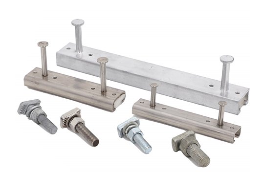
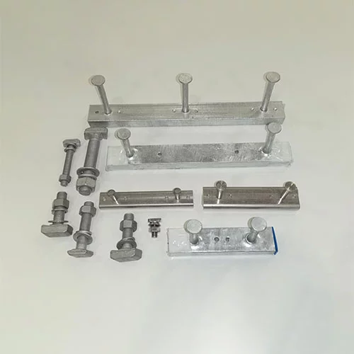
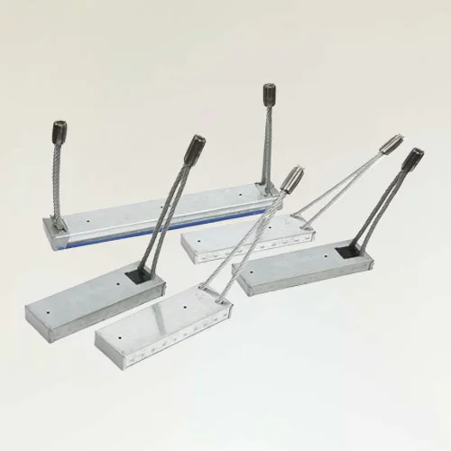
An anchor channel is a steel profile with a longitudinal slot, concrete-embedment anchors on the rear, and temporary protection that keeps the cavity clear. End caps and a removable filler strip are normally included. Matching T-bolts are inserted after the formwork or precast mould is removed.
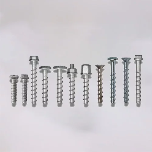
This product differs from a post-installed mechanical or chemical anchor. A conventional channel is positioned before casting; a post-installed anchor is drilled into hardened concrete. The methods follow different design rules and should not be substituted without approval.
Typical uses include facades, mechanical and electrical supports, tunnels, precast wall panels, lift systems, and equipment bases. The fixing point may be adjustable, but capacity applies only within the limits stated in the relevant product data.
How an Anchor Channel Carries Load
The load path begins at the T-bolt. Its head bears against the turned-in channel lips, creating a mechanical interlock. Force then spreads through the steel profile and into the welded or mechanically attached anchors. Finally, the anchors transfer tension, shear, or combined actions into the surrounding concrete.
Possible failure modes include channel yielding, lip deformation, anchor attachment failure, pull-out, and concrete fracture. Edge distance, anchor spacing, member thickness, and reinforcement can alter the result. Cracking also matters: a channel qualified only for uncracked concrete may be unsuitable where cracking is expected.
An anchor channel should therefore be treated as an engineered system. A capacity taken from one component cannot be applied to another with a different profile, anchor layout, bolt, concrete strength, or orientation.
Main Types of Anchor Channels
Profiles may be hot rolled or cold formed. Both can produce suitable products when design, material, and manufacturing controls are correct. Selection should follow approved section properties and system data; the production method alone does not establish a strength class.
Channels vary by size, slot width, steel grade, anchor configuration, length, coating, and intended loading. Accessories must match the series so that bolt engagement, end restraint, and clearances remain within the design assumptions.
What Determines Performance?
Geometry is fundamental. Wall thickness, lip shape, slot width, profile depth, and anchor spacing influence stiffness and resistance. The T-bolt must engage enough of the lip without binding or bearing on damaged edges.
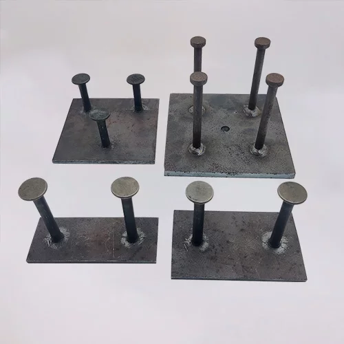
Material and fabrication also matter. Steel grade controls strength and ductility, while anchor geometry controls how force enters concrete. For welded anchors, size, penetration, placement, and defect control are critical.
Site conditions complete the picture. Design values depend on concrete strength, cracking status, edge distance, anchor spacing, member thickness, and load direction. Dynamic, fatigue, seismic, fire, or corrosive exposure may require further verification. A product selected for one support spacing may therefore be unsuitable when the layout or slab thickness changes.
Design and Specification Points
Designers should identify all relevant actions, including tension, shear, bending, eccentricity, vibration, and load combinations. These must be compared with the manufacturer's design method and approval scope. Pay particular attention to minimum edge distance, spacing, concrete thickness, and permitted bolt position.
Specify the channel type, dimensions, steel grade, anchors, slot width, length, coating, T-bolt, and accessories. When a formal approval or national standard applies, state its exact edition and limits.
Coordination matters. Formwork, reinforcement, embedded plates, and concrete cover can conflict with the anchor layout. Early review reduces site relocation and reinforcement cutting.
Where Anchor Channels Are Used
Facade systems use anchor channels for adjustable brackets, mullions, stone cladding, and curtain-wall components. Building services use them for pipe hangers, cable trays, and ventilation equipment. Precast producers embed them to create controlled connection points.
Infrastructure uses include tunnels, utility corridors, rail projects, and equipment rooms. Industrial plants use them around machinery and conveyors. Each application requires a separate review of loading, access, environment, and inspection.
Installing an Anchor Channel Correctly
Installation begins by checking delivered goods against the drawing and packing list. Confirm profile, length, anchor spacing, filler, end caps, and coating before fixing. The approved method must hold the unit at the correct elevation, line, and orientation. Temporary bracing should remain secure until the concrete can maintain the position.
Place and compact concrete without displacing the profile or damaging the filler. Excessive vibration nearby can create voids, move the unit, or deform thin sections. After stripping, inspect and clean the slot, then remove the filler completely so it cannot obstruct the T-bolt.
Use only compatible bolts and the specified tightening method. Repair coating on site cuts as required. Even a correctly positioned channel can be compromised by the wrong bolt, excessive torque, or unauthorised drilling.
Common Installation Mistakes
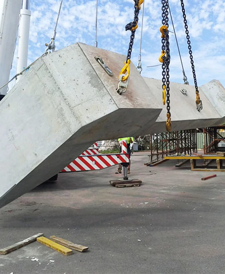
Common problems include insecure formwork fixing, missing end caps, filler displacement, concrete ingress, and careless vibration. Angled T-bolts, unmatched bolts, debris, and unrepaired cut edges are also hazards. Precast handling adds another risk because lifting, stripping, and transport can move an otherwise correctly placed insert.
Design errors include exceeding approved edge distance, ignoring concrete thickness, assuming a cracked-concrete rating, or mixing incompatible systems. Follow the manufacturer's instructions and approved drawings.
Quality Control and Documentation
Inspection begins with material traceability. Steel grade, heat number, dimensions, and mechanical properties must match the order. Production checks should cover profile width, depth, wall thickness, slot opening, straightness, length, anchor position, and weld quality. Check T-bolt fit because lip errors can block installation even when the outside looks correct.
Coating inspections should cover thickness, adhesion, appearance, and edge coverage. Load tests or approvals must match the exact construction. Records, certificates, packing lists, and batch identification allow the buyer to verify conformity. Accessories should remain identifiable by project, package, and channel series so that components for one system are not installed on another.
Choosing an Anchor Channel Supplier
A capable supplier should understand fabrication and system compatibility. Look for drawing review, controlled forming, accurate anchor placement, consistent welding, coating coordination, and traceable inspection. The supplier should also identify the correct T-bolts and accessories.
Compare more than cost per metre. Accessories, protective filler, documentation, coating repair, freight, and installation delays affect project cost. An incomplete quotation can appear cheaper while excluding essential items.
How HULK Metal Can Help
HULK Metal can review drawings for custom anchor channels, including dimensions, hole patterns, anchor arrangements, material selection, and surface treatment. Production planning can be coordinated with inspection and packing, while technical decisions follow the applicable project specification and product data.
Send quantities, destination, environment, connection details, and required certificates to obtain a practical proposal. Early review clarifies manufacturability and avoids unverified performance assumptions.
An anchor channel offers an efficient way to create adjustable concrete connections, provided the system is correctly matched and installed. Engineers should verify the load path and approval limits; contractors should protect position and slot cleanliness; buyers should confirm the complete scope of supply. Aligning design, manufacturing, and site work supports reliable connections.
Contact HULK Metal with technical requirements to discuss a suitable anchor channel solution.
Article Navigation
PRECAST CONCRETE ACCESSORIES
OTHER RELATED ARTICLE
- 1.How to Choose High-Quality Shuttering Magnetic Products and Suppliers Guide
- 2.Applications and advantages of swivel hoist rings: HULK Metal provides you with safer and more flexible lifting solutions
- 3.Lifting Clutch VS Lifting Ring Clutch:Definition, Working Principle, Application Scenarios, and Selection Guide
- 4.Lifting Anchors: An Essential Component in Construction and Heavy Lifting
Other Precast Concrete Accessories You Might Want to Know
You can click to learn more about HULK Metal precast concrete accessories such as lifting anchors, precast sockets, spread anchors, shuttering magnets, cast-in channels, wire loop boxes, and other precast concrete accessories you might want to know.