

Lifting Eye Anchor Tension Bar: What the Rated Load Assumes
Designing the Condition Behind a Cast-In Anchor's SWL
The safe working load forged onto a lifting eye anchor is often the only number written on the component. It is also the number least able to stand alone. A data sheet can describe the forged part, but it cannot compress every project condition into that mark. The rated value belongs to an installation: concrete, reinforcement, clutch engagement, load direction, and the tension bar passing through the eye.
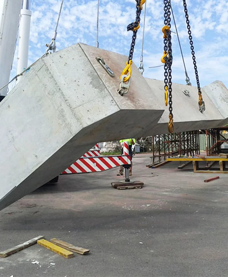
The eye anchor does not anchor itself. It creates an interface through which load leaves the lifting system and enters concrete; the bar on its far side completes the connection. This article follows that load path and examines the conditions the printed number assumes. The specific bar, geometry, angle, concrete strength, and embedment must come from approved design and product data.
A Number That Describes a System, Not a Part
Safe working load is not a statement that the anchor has a certain intrinsic strength in isolation. It is the load the complete lifting condition can tolerate under the assumptions used for its design. Force passes from the crane through the clutch, forged head and shank, eye, tension bar, and reinforcement into concrete. Each transition can govern the result.
The anchor occupies the middle of that chain. It includes the engagement head, body, and eye, but not the clutch, transverse bar, reinforcement cage, or concrete diffusion volume. The parameter table ends at the product; the load path does not. The rating therefore assumes that everything beyond that boundary completes the path without creating a weaker link.
The Assumption Is Distributed
The conditions behind SWL are distributed because the load path crosses more than one discipline. A lifting designer defines the force and reinforcement arrangement. The precast engineer translates it into the element. Production places and compacts concrete around the anchor and bar. The lifting team applies a force whose direction and timing may differ from the case assumed in a table.
No party necessarily sees the complete assumption at once. The supplier knows the compatible interface, the designer knows the element, the plant knows the cage and casting sequence, and the crew knows the final handling condition. Responsibility therefore becomes distributed rather than absent. The rating holds only while design intent, production geometry, and lifting method remain aligned.
What the Forged Eye Actually Asks of the Bar
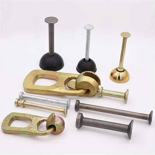
The eye is an interface, not an anchorage. Its opening locates the transverse bar and provides the point at which tension leaves the forged body. Once load reaches the bar, bar geometry, its continuation into the element, and the surrounding concrete govern how force enters the concrete.
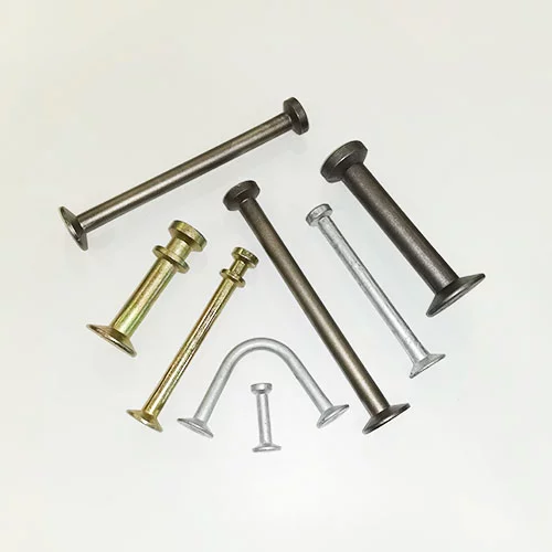
The bar performs three related tasks. It turns concentrated force at the eye into a broader contact and bond condition. It carries that force toward the reinforced core. It also constrains the concrete against splitting and local edge failure by tying the lifting zone into reinforcement that can distribute movement.
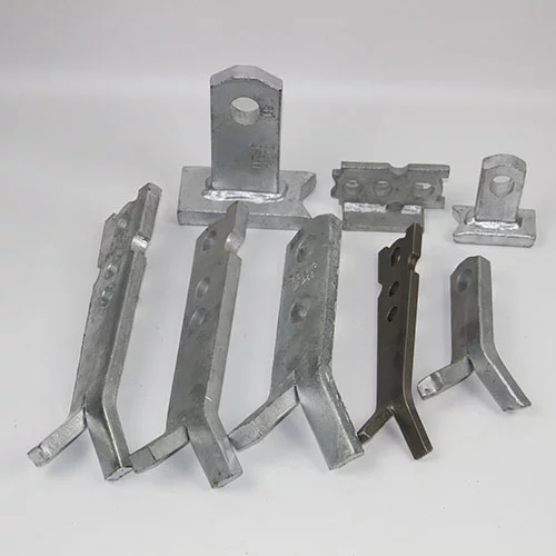
Where the approved design uses a V-shaped arrangement, the inclined legs can give force a more direct route into deeper concrete than a single bar close to the face. The opening creates two paths of resistance and spreads their influence across a larger diffusion volume. That does not make one angle universally preferable. The useful opening depends on available width, reinforcement-cage density, and expected load direction. A wider opening may conflict with other steel; a shallower one may keep force too near the lifting face. Correct geometry preserves the load path inside the actual element.
Horizontal tying to a lower mesh can integrate the lifting point with general reinforcement, but a straight tie does not automatically create the two-sided diffusion route of an approved V-shaped arrangement. It may suit the connection where the load path has been designed accordingly, but convenience at the eye should not be mistaken for anchorage.
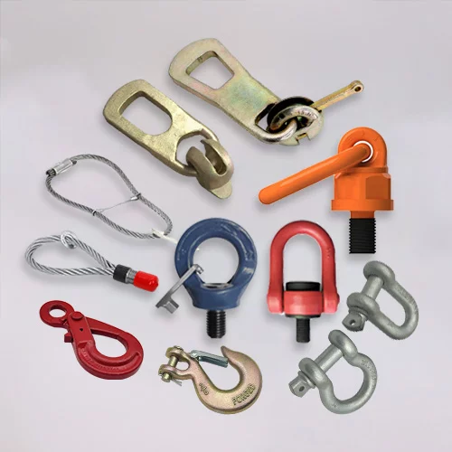
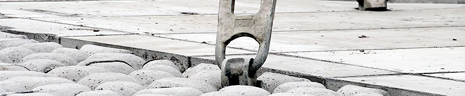
The eye is not a crane hook, and its opening is not intended to receive whatever shackle or sling fits. The lifting clutch engages the forged lifting head; the eye receives the cast-in tension bar. Nor is this anchor limited to a simple straight pull. It can belong to a system that handles other directions, but any increase in angle changes demand on bar, concrete, and clutch.
Four Conditions the Data Sheet Leaves to the Plant
The plant does not invent the engineering assumption, but it controls several variables through which that assumption becomes physical.
| Condition | Physical quantity changed | Normally defined through |
|---|---|---|
| Tension-bar specification and symmetric extension at both ends | Steel area, bond path, and balance of load away from the eye | Project lifting design and approved reinforcement drawing |
| Bend geometry | Direction of the force path, bearing zones, and available diffusion depth | Project design coordinated with element detailing |
| Position of the anchor through the wall thickness | Concrete cover, edge influence, and effective volume on each side of the eye | Approved layout and precast production plan |
| Compaction around the eye and bar | Steel-concrete contact and continuity of the load-transfer volume | Approved mix and placing method, executed during production |
Bar specification and extension change the steel available and the distance over which force can develop. If one side is shortened or its cage connection weakened, the load path becomes asymmetric. Bend geometry directs force and determines how much concrete lies between the bar and the nearest free surface. A drawing-perfect anchor still has an unsuitable diffusion volume if the bar turns too near a face.
Centering through wall thickness changes how force is shared across the concrete. A position close to one face concentrates splitting demand there. Compaction determines whether the modeled steel-concrete interface exists. A void near the eye or along the bar interrupts contact where the load path is most concentrated.
These are not finishing details added after the rated value has been established. They are inputs that allow the value to remain meaningful.
Where the Rated Value Stops Being Valid
The assumption fails when the space needed by the bar no longer exists. A narrow element may leave room for the forged body and recess former but not for the approved bend and extensions. Fitting a shorter bar changes the anchorage rather than preserving it. The issue is not anchor-body embedment; it is the arrangement space required by reinforcement through the eye.
A change in lifting direction also alters the bar's task. When the sling or load moves, a geometry developed for a dominant pull may place its legs in a different relation to that force. Anchor, bar, and concrete then experience another combination of tension, bearing, and splitting.
The assumption ceases to apply when lifting occurs before concrete can support the diffusion volume. The anchor may be embedded and the clutch correctly engaged, yet the surrounding material has not developed the resistance the design assumes.
In each case, the forged anchor is not necessarily failing at its material strength. The premise behind the rating has been compressed, redirected, or brought forward. The anchor is no longer used in the state the number describes.
Making the Implicit Explicit in Design Documents
The practical response is to make the system visible before it becomes hardware. A load-chain drawing should identify clutch engagement, forged body, eye, tension bar, reinforcement connection, and the concrete volume receiving the force. It belongs with the element design because it explains how the lifting point works, not merely what part was purchased.
Bar specification, bend, extension, and cage relationship should appear in the reinforcement information. Production can only preserve a dimension that has been defined. Anchor, recess former, and clutch should also be locked together as one interface system; a matching diameter is insufficient if their engagement details belong to different assemblies. Supply-side confirmation then concerns interface compatibility and batch conformity with the approved item.
The First Lift as a Check on the Assumption
The first lift is the earliest moment when the complete assumption can be observed together. The recess edge shows how concrete formed around the engagement zone. The element surface reveals local cracking or deformation. The clutch seat shows whether the removable interface fits as intended, while the element's attitude shows whether real force follows the expected direction.
These observations are feedback, not a substitute for the approved lifting procedure. A clean recess does not prove the intended bar extension; a level element does not prove adequate concrete condition. Together, however, they can reveal a mismatch between drawing and finished element. If the load path is orderly, the element should respond without unexplained cracking, bearing, or movement.
The rated load is not created solely by the forged anchor or purchased as a number on a certificate. It is designed into a system, built into the element, and preserved through handling. The tension bar carries the part of that proposition the anchor alone cannot.
Why HULK Metal
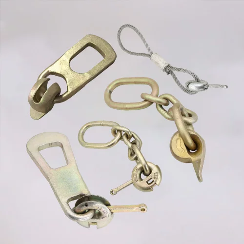
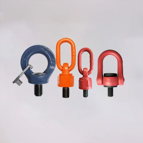
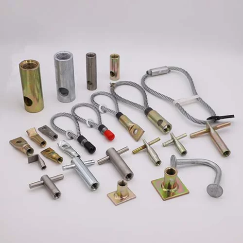
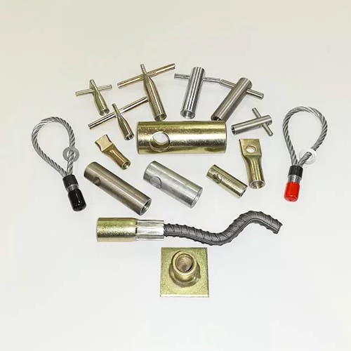
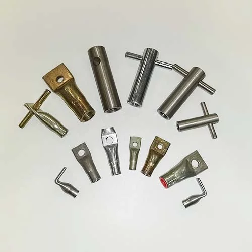
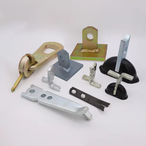
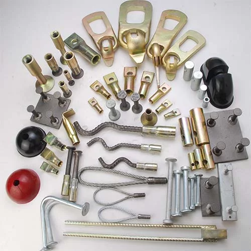
HULK Metal manufactures cast-in lifting anchors, recess formers, and compatible lifting devices as parts of a connected system. Its published range includes lifting eye anchors and lifting clutches, with production to drawings and requirements for material, dimensions, load group, and finish. That perspective matters when anchor, bar, recess, and clutch interface must be defined before casting.
The quality framework includes ISO 9001 control and product-specific CE documentation to be confirmed for the exact item and order. The project conversation begins with the approved load path: element drawing, reinforcement around the eye, lift direction, concrete condition, compatible clutch, and documentation.
Choose HULK Metal when the requirement is not simply an anchor marked with an SWL, but a matched lifting assembly around that value. The rating still depends on design and installation conditions; HULK Metal's contribution is to make the supplied hardware and interface reproducible to the approved specification.
Article Navigation
PRECAST CONCRETE ACCESSORIES
OTHER RELATED ARTICLE
Other Precast Concrete Accessories You Might Want to Know
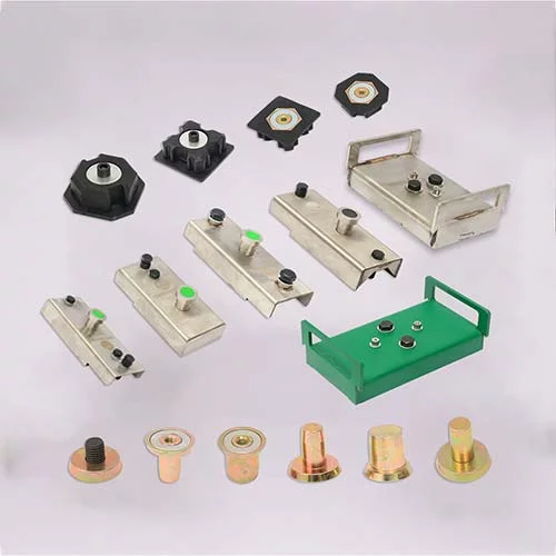
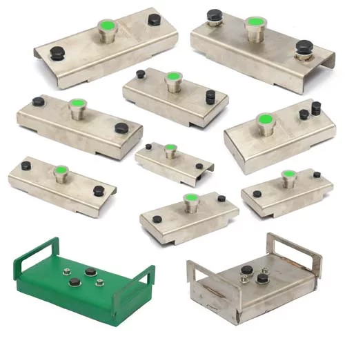
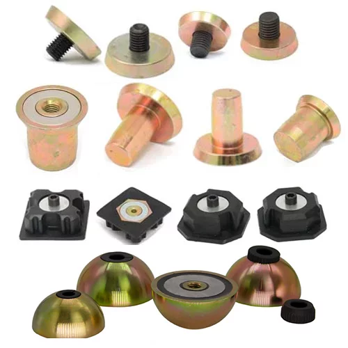
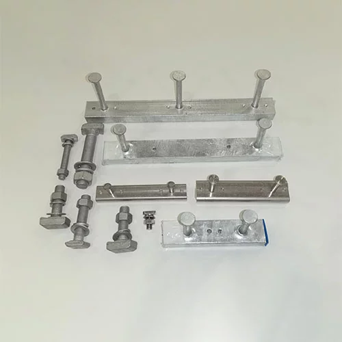
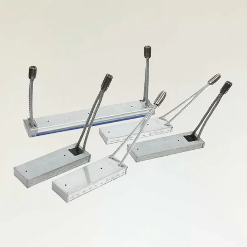
You can click to learn more about HULK Metal precast concrete accessories such as lifting anchors, precast sockets, spread anchors, shuttering magnets, cast-in channels, wire loop boxes, and other precast concrete accessories you might want to know.